2.4.1 Boolean logic
Simple Logic Diagrams Using the Operators AND, OR, and NOT
Introduction: Logic diagrams are graphical representations of logical expressions or statements. They use symbols to represent logical operators and variables, making it easier to understand and analyze logical relationships. In this study guide, we will focus on three fundamental logic operators: AND, OR, and NOT.
Section 1: The AND Operator
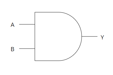
Explanation: The AND operator combines two or more conditions and returns true only if all conditions are true. It can be represented in a logic diagram using the symbol (∧) or the word "AND."
Example: Let's consider a simple scenario where we have two conditions: A is true and B is true. The AND operator would evaluate the logic as (A ∧ B). The output will be true only if both A and B are true.
Logic Diagram:
Section 2: The OR Operator
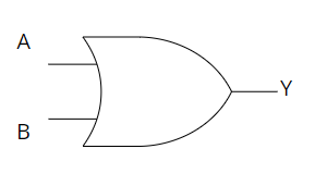
Explanation: The OR operator combines two or more conditions and returns true if at least one of the conditions is true. It can be represented in a logic diagram using the symbol (∨) or the word "OR."
Example: Let's consider a scenario where we have two conditions: A is true and B is false. The OR operator would evaluate the logic as (A ∨ B). The output will be true because at least one of the conditions (A) is true.
Logic Diagram:
Section 3: The NOT Operator
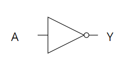
Explanation: The NOT operator takes a single condition and returns the opposite value. It can be represented in a logic diagram using the symbol (¬) or the word "NOT."
Example: Let's consider a scenario where we have a condition A that is true. The NOT operator would evaluate the logic as (¬A). The output will be false because the NOT operator flips the value of A.
Logic Diagram:
Truth Tables
Introduction: Truth tables are graphical representations used to show the possible outcomes of logical expressions. They help us understand how the values of inputs affect the output of a logical expression. In this study guide, we will explore how to create and interpret truth tables.
Section 1: Constructing a Truth Table
Explanation: To construct a truth table, we list all possible combinations of input values and evaluate the logical expression for each combination. The columns represent the inputs, and the last column represents the output.
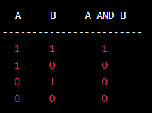
Example: Let's consider a simple logical expression: A AND B. We have two inputs, A and B, and each input can have two possible values (true or false). By considering all possible combinations of A and B, we can construct a truth table.
Truth Table for A AND B:
Section 2: Interpreting a Truth Table
Explanation: Interpreting a truth table involves understanding the relationship between inputs and the resulting output. It helps us identify patterns and make conclusions about the behavior of logical expressions.
Example: Using the truth table above, we can interpret the logical expression A AND B as follows:
- When both A and B are 1, the output is 1.
- In all other cases, when at least one of A or B is 0, the output is 0.